khanh nguyen
During Spring 2017, I participated in a UROP in the Digital Structures group under faculty advisor Caitlin Mueller and graduate supervisor Yijiang Huang. I worked on an ongoing project, Robotic Print, used 3D printing hardware attached to a KUKA robotic arm to create complex 3D-printed structures that could print in mid-air. The arm allowed for flexibility in the prints because it could follow different paths for optimal printing, instead of being confined to the layer-by-layer back-and-forth of a normal 3D printer.
During my time with the group, the project was two-pronged: Caitlin and Yijiang wanted to integrate the path optimization algorithm into a web visualization platform that designers and architects could use easily. In addition, they wanted to experiment with different extruder and hot-end designs to test what would work best and improve on their already-working model. At the time, the hardware setup was attached to a robotic arm in the Architecture Fab Lab, with the electronics spread around it. In order to better test out different designs, we decided to design a platform that made the setup more compact and mobile.
My job was to design a way to encase the electronics and controls that would integrate with the platform for the hardware that another mechanical engineering UROP, Kodiak, was building. My solution was to have two laser-cut boxes, the first one with the button and LCD screen press-fit and a hidden power supply and the second one with all of the circuits mounted and a clear top so that we could see the signal LEDs. I soldered and mounted new circuits to create a duplicate of the original setup, and tweaked the arduino code of the stepper motor that controlled the extrusion to make sure it was functioning. I made sure that the wires and connections were as neat and simple as possible, so that the project was portable and could easily integrate with other components.
The other part of my job was to take photographs and video to help document the project. This included experimenting with a thermal camera.
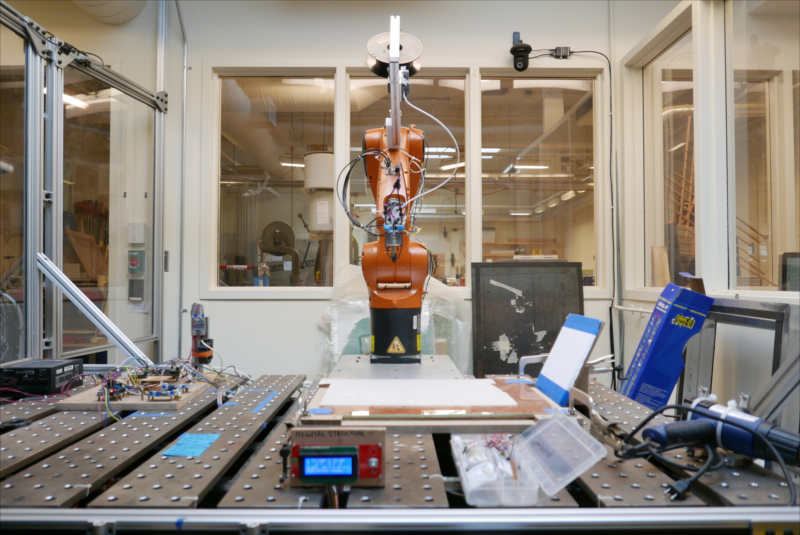
The layout of the robotic arm and 3D print hardware, along with the associated circuitry.
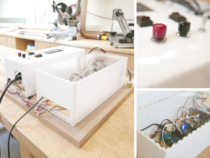
My final design, with the circuitry.
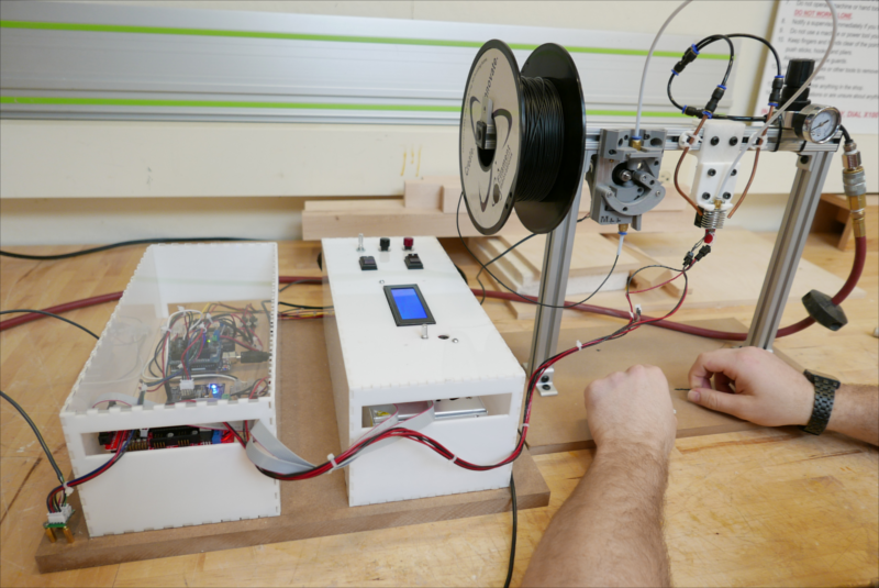
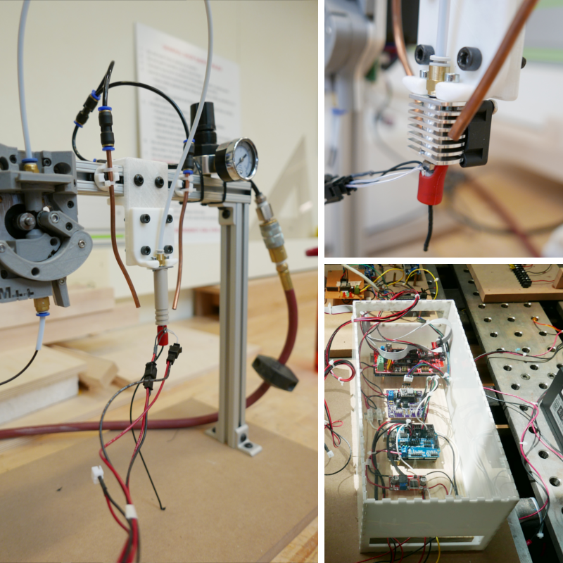
The integration of my design with the extrusion frame.
The electronics at work! The portable design successfully extrudes.
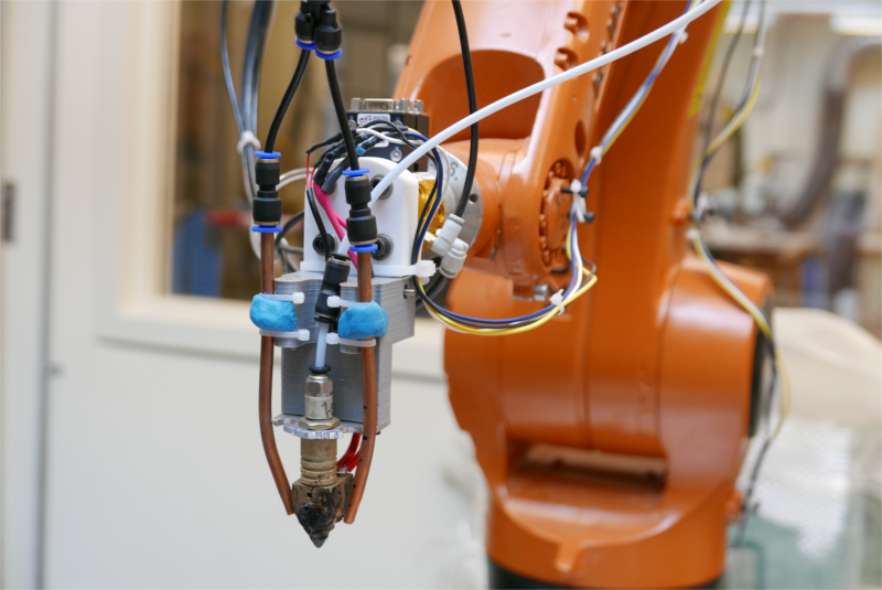
A closeup of the old design on the robotic arm.
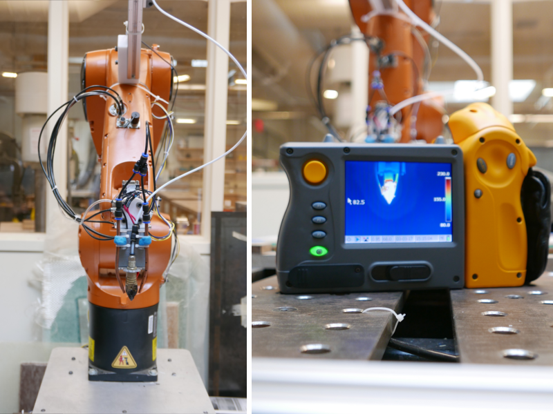
Testing the extrusion with a thermal camera.
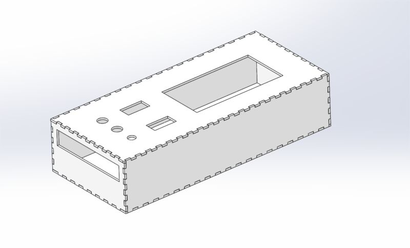
I played with appropriate dimensions for the designs using Solidworks.